Total Dynamic Head (TDH) Calculation: Engineering Guide for Pump Sizing
Dec 30, 2025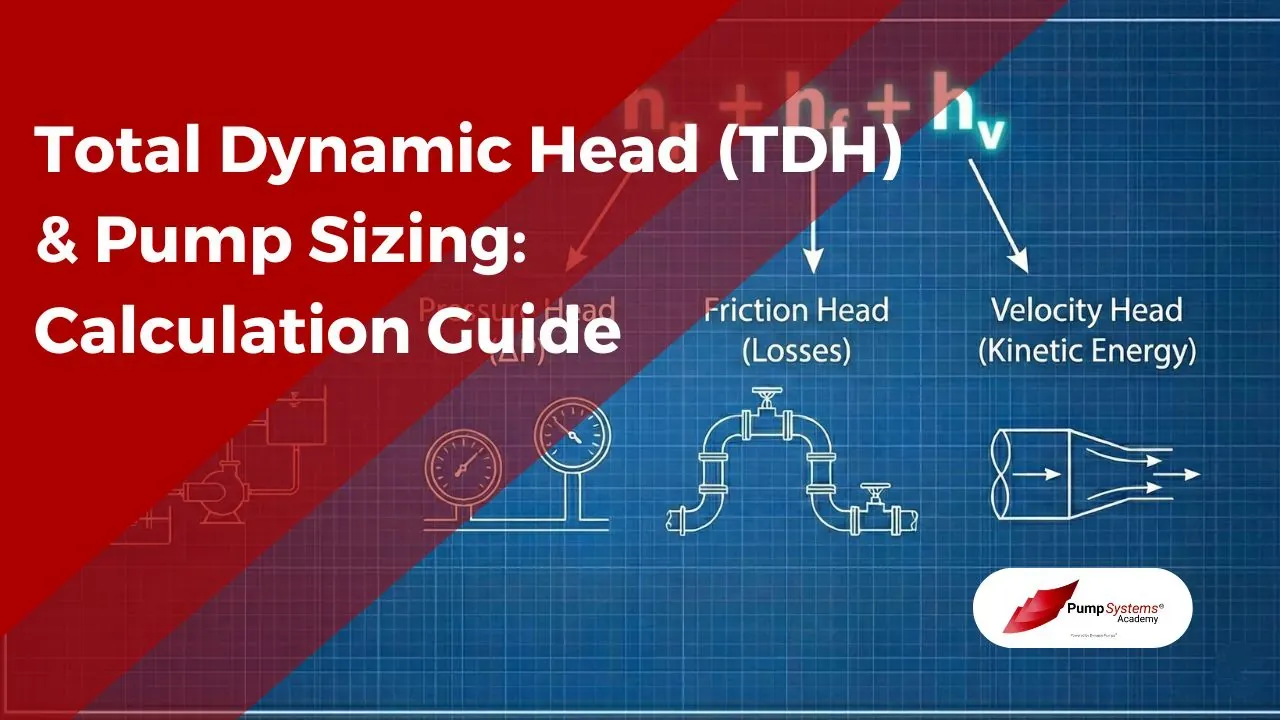
Engineers rarely struggle with the idea of “head,” but many systems fail on the arithmetic and sign conventions. A correct total dynamic head calculation turns a messy piping sketch, a few elevations, and scattered gauge readings into one number the pump must supply at a stated flow. That number is not just lift. It is lift plus losses plus any required pressure rise, all expressed as energy per unit weight.
A quick total dynamic head calculation roadmap
A reliable workflow starts by choosing two stations for Bernoulli’s principle, usually a suction reference point and a discharge reference point, then expressing every term in consistent head units (ft or m of the pumped liquid).
- Pick control points: free surfaces for open tanks, or nozzle centerlines for closed vessels
- Normalize everything to head: elevations, gauge pressure differences, friction and minor losses, and any velocity head change
- Check the physics: sign conventions, gauge versus absolute pressure, and whether velocity head cancels
What is Total Dynamic Head (TDH)?
Total Dynamic Head (TDH) is the total energy per unit weight that the pump must impart to the fluid to move it from the source to the destination at a specified flow rate. It is reported as a length of fluid column, for example feet of water (ft H₂O) or meters of liquid (m).
TDH is best viewed as a bookkeeping result from Bernoulli’s principle with a pump term added and with losses subtracted. In that framing, the pump supplies head so the fluid can (1) rise in elevation, (2) reach a higher pressure environment, and (3) overcome irreversible losses due to friction and fittings, plus any change in kinetic energy.
A common source of confusion is vocabulary. Static head refers to elevation change (and, in many engineering notes, any “static” pressure difference between reservoirs). Dynamic head refers to flow-dependent contributions, mainly friction and sometimes velocity head. TDH combines both.
The Four Components of TDH
TDH is typically decomposed into four additive terms. Even when a term is small, keeping it visible helps prevent hidden assumptions.
TDH = hs + hf + hp + hv
Where:
- hs = static (elevation) head
- hf = friction head (major + minor losses)
- hp = pressure head (required pressure rise between endpoints)
- hv = velocity head difference between endpoints
A compact way to remember what changes with flow is that (hs) is usually independent of flow, while (hf) grows strongly with flow (often close to (Q^2) in turbulent pipe flow), and (hv) matters when cross-sectional areas differ.
The table below summarizes typical behavior and common units.
|
Component |
Physical meaning |
Typical dependence on flow |
Common pitfalls |
|---|---|---|---|
|
Static head (hs) |
Elevation head between endpoints |
None (for fixed levels) |
sign errors with suction lift |
|
Pressure head (hp) |
Required pressure rise between endpoints |
None if endpoints fixed |
mixing gauge and absolute pressure |
|
Friction head (hf) |
Irreversible losses (major + minor) |
Strong, often (proportional to Q^2) |
missing fittings, wrong roughness, wrong (f) |
|
Velocity head (hv) |
Change in kinetic energy |
(proportional to v^2) |
ignored when diameters change sharply |
The General TDH Formula Explained
A Bernoulli-style expression between a suction station (1) and a discharge station (2) is:
H_pump = (z2 - z1) + (p2 - p1) / (rho * g) + (v2^2 - v1^2) / (2g) + hL
Here (h_L) is the sum of losses (major and minor). Engineers often rename the grouped terms into the four-component TDH form:
TDH = hs + hp + hv + hf
with:
- hs = z2 - z1 (elevation head)
- hp = (p2 - p1) / (rho * g) (pressure head)
- hv = (v2^2 - v1^2) / (2g) (velocity head difference)
- hf = hL (friction and minor-loss head)
Two clarifications matter in practice. First, “pressure head” should be computed from the pressure difference between the chosen endpoints, not from a single gauge reading in isolation. Second, “pressure” in Bernoulli is absolute pressure, while many field instruments read gauge pressure. Gauge pressure is usable if both endpoints are treated consistently and atmospheric pressure cancels.
Calculating Static Head: Suction Lift vs Flooded Suction
Static head is anchored to a datum and a sign convention. A common convention takes upward elevation change as positive, so hs = z_discharge - z_suction.
Two inlet arrangements dominate pump station layouts:
Suction lift occurs when the pump centerline is above the liquid surface in the source. In that case the suction surface elevation is below the pump, and static head includes a negative suction contribution when referenced to the pump.
Flooded suction occurs when the pump centerline is below the source liquid surface. The fluid at the pump suction is positively pressurized by the elevation head above the pump, which improves NPSH available and generally simplifies priming and cavitation control.
A useful mental check is atmospheric pressure. A large suction lift pushes suction absolute pressure downward, sometimes close to vapor pressure, which can induce cavitation even if the TDH arithmetic looks reasonable. That is not a TDH correction, it is a separate suction-side feasibility check.
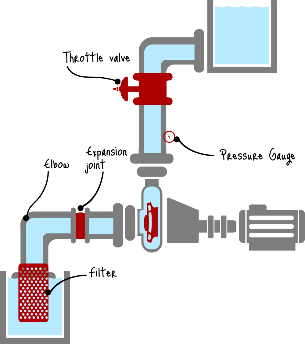
Calculating Friction Head Losses
Friction head collects losses from straight pipe (major losses) and from components that disturb the flow (minor losses). For many water and process systems, friction dominates the difference between a “back of the envelope” lift and the real TDH at design flow.
For major losses, Darcy-Weisbach is the general-purpose choice:
hf_major = f * (L/D) * (v^2 / 2g)
The Darcy friction factor (f) depends on Reynolds number and relative roughness, typically obtained from the Moody chart or computed with a correlation (Colebrook-White, Swamee-Jain, and related fits). Hazen-Williams is also used for water distribution work, but it is empirical and not recommended for arbitrary fluids or wide viscosity ranges.
For minor losses, a common expression is:
hf_minor = Sum(Ki) * (v^2 / 2g)
A field-friendly alternative is the equivalent length method, which replaces each fitting by an equivalent straight length (L_{eq}) at the same diameter and then folds it into Darcy-Weisbach via an effective L_total = L + Sum(L_eq). That method is convenient when a pipeline is long and fittings are numerous, and it naturally keeps the calculation in one formula.
One practical caution is that minor losses can dominate in compact skids, short manifolds, or valve stations where straight length is small but fitting count is high.
Converting Pressure Readings to Head
Pressure-to-head conversion is the hinge between field instruments and pump-system energy accounting. A gauge may read PSI, but TDH must be summed in feet (or meters) of the pumped liquid.
For US customary units, the standard conversion is:
Head (ft) = (PSI * 2.31) / SG
where (SG) is the specific gravity of the pumped liquid relative to water at the reference condition. The factor 2.31 is the head of water corresponding to 1 psi.
This leads to an important statement that students often memorize incorrectly. Head is expressed as energy per unit weight and is commonly used in pump curves independent of density, while pressure depends directly on density. A pump delivering 100 ft of head produces different pressure depending on the fluid. If (SG = 0.8), 100 ft of head corresponds to a smaller pressure than it would for water.
A pressure-reading sanity check also requires distinguishing gauge pressure from absolute pressure. Gauge pressure is referenced to local atmospheric pressure. Absolute pressure is referenced to vacuum. Bernoulli’s equation is written in absolute terms, but gauge values are still workable in TDH if both endpoints are expressed on the same gauge basis and the atmosphere cancels.
Worked Example: Calculating TDH for a Water Transfer System
Consider a pump transferring water from a pit to an atmospheric tank.
Scenario and given values
- Pumping water at Q = 500 GPM
- Pit free surface is 10 ft below the pump centerline (suction lift)
- Tank free surface is 50 ft above the pump centerline
- Total friction losses at 500 GPM: hf = 15 ft
- Tank pressure is 0 psig (atmospheric at discharge surface)
Step 1: Static head (hs)
Choose the suction reference at the pit free surface and the discharge reference at the tank free surface. With the pump centerline as the intermediate datum:
- Suction elevation: z1 = -10 ft
- Discharge elevation: z2 = +50 ft
So:
hs = z2 - z1 = 50 - (-10) = 60 ft
Step 2: Pressure head (hp)
Both endpoints are open to atmosphere, so their gauge pressures are equal (0 psig at each free surface). The pressure difference is zero:
hp = 0
Step 3: Velocity head difference (hv)
At free surfaces in large reservoirs, velocity is effectively zero. With that choice of endpoints:
hv = (v2^2 - v1^2) / 2g ≈ 0
If instead the endpoints were placed at pipe centerlines with different diameters, (hv) would need explicit evaluation via (v = Q/A) and (v^2/(2g)). Many plant water-transfer lines have the same suction and discharge pipe size, so the velocity head difference often cancels even when endpoints are taken at nozzles.
Step 4: Friction head (hf)
Given directly:
hf = 15 ft
Step 5: Total Dynamic Head
TDH = hs + hp + hv + hf = 60 + 0 + 0 + 15 = 75 ft
So, at 500 GPM, the pump must supply 75 ft of head for this system.
A compact interpretation is that 60 ft is non-negotiable gravitational work, while 15 ft is the flow-dependent penalty paid to Darcy-Weisbach friction and minor losses.
How TDH Relates to the System Curve
For many pipe networks operating in turbulent flow, friction losses scale approximately with the square of flow rate. A common system-curve model is:
H_system(Q) = H_static + kQ^2
where (H_static) is the zero-flow intercept (static plus any fixed pressure requirements) and (kQ^2) aggregates major and minor losses.
The pump has its own head-capacity curve at a given speed. The intersection of the pump curve and the system curve defines the operating point. If the estimated TDH is too low, the predicted operating point shifts to higher flow than the system can actually sustain, and the real operating point moves back along the pump curve to a lower flow.
System curves also explain why small changes can matter. Closing a valve increases minor losses and effectively raises (k), steepening the curve. Pipe aging increases roughness and raises (f), with similar effect. Changes in tank level alter the intercept term (H_static) without changing the curvature.
Common Errors in Head Calculation
Many TDH failures are not advanced fluid mechanics mistakes. They are bookkeeping errors that propagate into pump selection, energy use, and operability.
A short checklist helps catch the recurring problems:
- Wrong reference elevations: mixing pump centerline, nozzle elevations, and liquid surfaces
- Unit inconsistency: adding psi directly to feet, or mixing ft and m inside one sum
- SG omission: treating 2.31 ft/psi as universal, even when (SG ≠ 1)
- Fittings ignored: missing check valves, strainers, partially closed isolation valves, or control valves
- Velocity head neglected in contractions: large diameter change near discharge nozzles, headers, or orifice-like restrictions
A second, more subtle class of errors comes from pressure measurements. Gauge taps placed too close to elbows or reducers can carry local dynamic effects that are not representative of average static pressure, so a pressure-based TDH estimate benefits from straight-run taps and stable flow conditions.
FAQs
These questions are phrased the way they tend to appear in design reviews and pump troubleshooting notes.
1. What is the difference between static head and dynamic head?
Static head is driven by elevation change (and often fixed endpoint pressures), independent of flow. Dynamic head refers to flow-dependent contributions, mainly friction losses and sometimes velocity head changes.
2. Does pipe diameter affect the total dynamic head calculation?
Yes. Diameter changes velocity and Reynolds number, which drives both friction loss and velocity head, so TDH at a given flow can change significantly with diameter.
3. How do I calculate TDH using pressure gauges on an existing pump?
Convert the measured differential pressure (discharge minus suction) to head, then correct for elevation difference between taps and include any velocity head difference if pipe sizes differ at the taps.
4. Why is Specific Gravity important when converting PSI to Head?
Because pressure depends on density. The conversion (Head (ft) = (PSI * 2.31) / SG) shows that the same PSI corresponds to more head for lighter fluids and less head for heavier fluids.
5. Does the pump create pressure or head?
It creates head as energy per unit weight. Pressure is the local manifestation of that head in a given fluid and system geometry.
6. What happens to the flow rate if I underestimate the TDH?
The real system curve sits above the calculated one, so the operating point shifts to lower flow than predicted, sometimes far enough to miss process requirements.
7. How do I account for elbows and valves in the TDH calculation?
Use minor-loss (K) values with (K v^2/(2g)), or convert each fitting to an equivalent length and add it to straight-pipe length in Darcy-Weisbach.
8. Is Velocity Head always necessary to include?
No. It is often negligible or cancels when suction and discharge diameters are the same and endpoints are large reservoirs, but it matters with strong diameter changes or high velocities.
9. Can Total Dynamic Head change over time in a system?
Yes. Fouling, corrosion, valve position changes, and equipment additions change friction and minor losses, shifting the system curve and the TDH at a given flow.
10. What is the difference between Suction Lift and Suction Head?
Suction lift means the pump is above the source liquid surface and must draw fluid upward, reducing suction pressure. Suction head (flooded suction) means the pump is below the source surface and has positive inlet head.
