Specific Speed (Ns) & Suction Specific Speed (Nss): Formulas & Calculation Guide
Jan 21, 2026
Engineers often reach for a single index when they want to predict a centrifugal pump’s “personality” before seeing a drawing. That index is specific speed, and it becomes far more useful once it is treated as geometry encoded in a number, not as a literal operating speed. Early in coursework and later in design reviews, the pump specific speed formula is the compact bridge between a duty point and an impeller profile that can realistically deliver it.
What is Specific Speed (Ns) and Why Does It Matter?
Specific Speed (Ns) is best described as a similarity index. It compares geometrically similar pumps by answering a focused question: What impeller shape would be required to produce a given flow at a given head when rotating at a given speed? In that sense, Ns is a classifier of hydraulic design.
Ns is often called “dimensionless” in turbomachinery theory, yet many day-to-day calculations use US customary inputs (rpm, gpm, ft) or common SI inputs (rpm, m³/s, m). The numerical result then depends on the chosen unit convention. Even with that practical caveat, Ns remains an effective dimensionless number in the conceptual sense: it identifies families of impeller geometry, and it anticipates curve behavior.
The engineering payoff is immediate. A duty point with high head and modest flow pushes Ns downward, signaling a radial-flow centrifugal impeller with narrow passages. A duty point with huge flow and small head pushes Ns upward, signaling a mixed-flow or axial-flow impeller where the hydraulic design prioritizes throughput.
After a duty point is mapped to an Ns range, an engineer can infer more than “radial vs axial.” Ns correlates with expected shutoff head ratio, likely efficiency island width, sensitivity to operating away from BEP, and the way shaft power changes toward shutoff.
A practical way many engineers remember the visual connection is to tie Ns to flow direction through the impeller:
- Low Ns: radial flow dominates, high head capability, smaller suction eye relative to impeller OD.
- High Ns: axial flow dominates, low head capability, large suction eye and propeller-like blade loading.
Symbols and BEP Conventions
Specific speed is defined at the best efficiency point (BEP) of the pump stage under discussion. That “stage” wording matters in multistage machines, and “per eye” matters in double-suction designs.
Before any arithmetic, the variables must be pinned down consistently:
- Speed, N: shaft rotational speed, typically in rpm.
- Flow, Q: flow at BEP for the hydraulic element being evaluated (stage, and per suction eye when applicable).
- Head, H: developed head at BEP for that stage, not system head and not shutoff head.
- BEP discipline: Ns computed off-design loses its intended geometric meaning, because the same impeller can exhibit very different H and Q away from its design incidence.
For reliability engineers, the BEP convention is more than academic. The stable operating window is anchored to BEP because internal recirculation and hydraulic radial thrust rise sharply as operation moves far left or far right of that point.
The Specific Speed Formula (US Customary vs Metric)
The algebraic form is the same across unit systems, but the numeric result is not. The formula below is the common North American convention that uses gpm and feet:
Ns = (N * Q^0.5) / H^0.75 (Where N=RPM, Q=GPM, H=Head in ft).
In SI work, engineers often keep rpm for N but use metric flow and head. The same structure is used, with Q in m³/s and H in m. Some catalogs use m³/h, which changes the numeric value again. The key is consistency with the charts or acceptance criteria being used.
A compact reference table helps prevent cross-unit confusion during reviews.
|
Item |
US customary convention |
SI convention (common in analysis) |
Notes |
|---|---|---|---|
|
Speed (N) |
rpm |
rpm |
Some texts use r/s; the number shifts accordingly |
|
Flow (Q) |
gpm |
m³/s (or m³/h in some catalogs) |
Always state which one was used |
|
Head (H) |
ft |
m |
Use pump developed head at BEP |
|
Formula form |
Ns = (N * Q^0.5) / H^0.75 |
Ns = (N * Q^0.5) / H^0.75 |
Same exponents, different numeric result |
When comparing two pumps, the safest practice is to compute Ns using the same unit convention for both, then interpret the result with the matching Ns ranges. Mixing a US Ns number with an SI-based chart is a quiet way to misclassify an impeller.
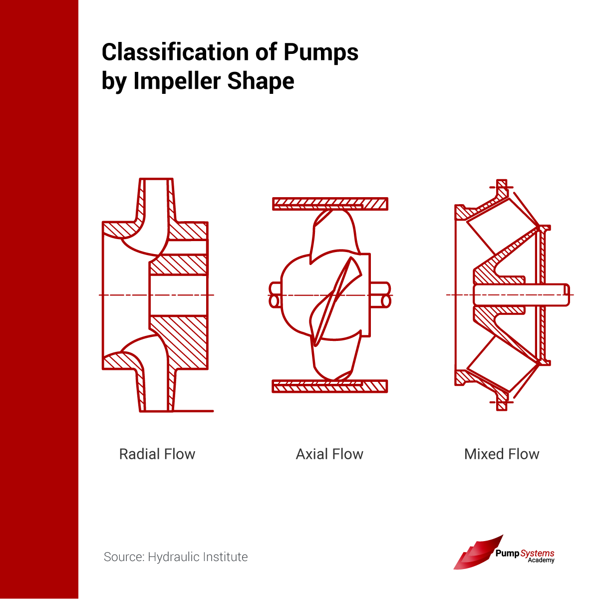
How Ns Determines Impeller Geometry (Radial vs Axial)
Ns maps strongly to impeller profile because the head and flow targets impose different velocity triangles and passage proportions. Low Ns designs require higher head per stage, so they emphasize tangential velocity and diffusion, typically with backward-curved blades and tighter flow areas. High Ns designs require high flow per stage, so they emphasize larger flow passages and more axial guidance.
A simple set of ranges is widely used as a visual rule-set:
- Low Ns (500–1000): radial flow, narrow impellers, high head, low flow.
- Medium Ns (2000–4000): Francis vane (mixed flow).
- High Ns (9000+): axial flow (propellers), low head, huge flow.
Those numbers are most commonly quoted in US customary form. They should be treated as overlapping bands rather than rigid bins, because casing style, specific diameter, diffuser design, and suction geometry can shift where a pump “feels” radial or mixed in practice.
Mixed-flow impellers are often the least appreciated category among students, yet they dominate many real services because they balance head capability with reasonable NPSH behavior. Their exit flow angle is oblique: neither purely radial nor purely axial. That compromise shows up as broader efficiency islands and moderately flat H-Q curves.
Ns also affects discharge specific speed and diffuser choices. For a given impeller Ns, the designer’s downstream hydraulic design must convert kinetic energy to pressure without separation. High Ns stages tend to carry higher absolute flow velocities, pushing the diffuser or volute design toward larger areas and gentler diffusion to preserve efficiency.
Understanding Suction Specific Speed (Nss)
Suction Specific Speed (Nss) is the suction-side companion to Ns. It classifies inlet hydraulic aggressiveness by replacing developed head with NPSH required (NPSHr). The intent is direct: it correlates suction geometry with how “demanding” the impeller eye is in terms of inlet pressure.
The plain-text form used widely in US customary work is:
Nss = (N * Q^0.5) / NPSHr^0.75 (Crucial: uses NPSH required instead of Head).
Because NPSHr is not a fluid property but a pump test result tied to cavitation criteria, Nss becomes a design and selection index rather than a thermodynamic guarantee. It is still extremely valuable in reviews because it forecasts the trade space between low NPSHr and stable inlet behavior.
One important detail is how Q is chosen in double-suction pumps. Many engineering groups use flow per eye in the Nss equation, because each eye “sees” roughly half the total flow. A reliability review should always state whether the Nss calculation used total flow or per-eye flow, since the square-root dependence means the number will shift materially.
The "Nss 11,000" Rule: Balancing Efficiency vs Reliability
A recurring guideline in pump engineering is the caution threshold near Nss = 11,000 (US customary units). It is best treated as a reliability flag, not a universal prohibition.
The underlying mechanism is geometric. High Nss pumps achieve low NPSHr by making it easy for fluid to enter the impeller: large suction eyes, generous inlet areas, and inlet blade angles that reduce acceleration and incidence losses. Those choices reduce required inlet pressure, which is attractive in cooling water, condensate, and other low-NPSHa services.
Yet the same large-eye geometry can produce a narrower stable operating window. When a high Nss pump operates far from BEP, the inlet flow can lose its designed incidence and begin to separate. That separation frequently manifests as inlet-side internal recirculation. It can raise vibration, increase noise, erode surfaces, and destabilize seal and bearing life even when classic cavitation damage is not obvious.
A reliability-focused interpretation often sounds like this: a pump selected primarily for minimum NPSHr can be easier to cavitate less at BEP, but harder to operate stably away from BEP. Nss above 11,000 is where many standard designs begin to show that trade more sharply, especially in water-like fluids.
Many engineers summarize the practical implications in a short checklist:
- Low NPSHr: improved suction capability on paper, often a selling point in procurement.
- Large suction eye: higher sensitivity to inlet distortion and off-design incidence.
- Operating range: narrower stable operating window as Nss rises, especially left of BEP.
- Observed symptoms: internal recirculation, rising vibration, and accelerated wear when throttled deeply.
That is why the “Nss 11,000” discussion belongs in both design and operations meetings. The selection decision can be correct for NPSHa and still be fragile when plant reality forces extended operation away from BEP.
Calculating Ns and Nss: Step-by-Step Examples
The mathematics is simple; the discipline is in data selection and unit consistency. The examples below use the plain-text formulas and US customary units.
Example 1: Moderate head, moderate flow (radial to mixed-flow tendency)Given BEP conditions: N = 1780 rpm, Q = 1500 gpm, H = 120 ft, NPSHr = 15 ft.
- Compute √Q = √1500 ≈ 38.73
- Compute H^0.75 = 120^0.75 ≈ exp(0.75 ln 120) ≈ exp(0.75 × 4.787) ≈ exp(3.590) ≈ 36.2
- Ns = (1780 × 38.73) / 36.2 ≈ 1904
- Compute NPSHr^0.75 = 15^0.75 ≈ 8.04
- Nss = (1780 × 38.73) / 8.04 ≈ 8570
Interpretation: Ns around 1900 sits in a radial to mixed-flow neighborhood. Nss around 8600 is below the 11,000 caution threshold, often consistent with a more forgiving suction design.
Example 2: High flow, low head (mixed to axial tendency)Given BEP conditions: N = 1180 rpm, Q = 20,000 gpm, H = 25 ft, NPSHr = 12 ft.
- √Q = √20000 ≈ 141.42
- H^0.75 = 25^0.75 ≈ exp(0.75 ln 25) ≈ exp(0.75 × 3.219) ≈ exp(2.414) ≈ 11.18
- Ns = (1180 × 141.42) / 11.18 ≈ 14930
- NPSHr^0.75 = 12^0.75 ≈ exp(0.75 ln 12) ≈ exp(0.75 × 2.485) ≈ exp(1.864) ≈ 6.45
- Nss = (1180 × 141.42) / 6.45 ≈ 25880
Interpretation: Ns near 15,000 indicates an axial-flow style hydraulic design. The very high Nss signals a strong emphasis on low NPSHr, with the associated risk that operation far from BEP may invite inlet instability and internal recirculation unless the design and operating controls address it.
Low Ns vs High Ns: Performance Curve Characteristics
Specific speed does not just classify impellers; it anticipates curve shape.
Low Ns pumps (radial-flow) usually have a steep head-capacity curve. Shutoff head is comparatively high, and head drops quickly as flow increases. They also commonly exhibit a non-overloading power characteristic where brake horsepower decreases toward shutoff. That behavior is operationally forgiving: starting against a closed discharge valve tends to be less demanding on the driver.
High Ns pumps (axial-flow) tend to have flatter head-capacity curves, and their power curve can rise at shutoff. That is a critical operational difference. Starting an axial-flow pump against a closed valve can demand high torque and high current because the hydraulic loading does not fall away as flow approaches zero. Reliability engineers often pair that fact with strict start-up procedures and motor margin checks.
The curve-shape implications connect back to internal hydraulics:
- High Ns impellers pass large flow areas, so off-design operation can produce larger incidence errors and stronger recirculation zones.
- Low Ns impellers diffuse energy more aggressively, so they often show larger shutoff head ratios and sharper efficiency peaks.
Those tendencies do not replace actual test curves, but they explain why a pump “feels” stable or sensitive in the field.
Common Misconceptions About Specific Speed
Specific speed is frequently misused in conversations, especially when it is treated as a property of the motor rather than the pump stage.
A recurring misconception is that Ns is “the speed a pump runs at.” It is not. Ns is an index computed from speed, flow, and head at BEP, and it primarily describes impeller geometry and geometric similarity.
Another misconception is that higher Ns always means higher efficiency. Many high Ns machines can reach excellent efficiency at very high flows, but low Ns pumps can also be highly efficient in high-head services. Efficiency follows careful hydraulic design, surface finish, clearances, and Reynolds number effects, not just Ns.
A third misconception is that Nss above 11,000 automatically means a pump is “bad.” The more defensible statement is narrower: in many water-like services and standard designs, Nss above 11,000 often correlates with a narrower stable operating window and a higher likelihood of off-design inlet problems. Context matters: fluid, suction piping quality, inducer use, operating controls, and how tightly the pump is held to BEP all change the risk picture.
FAQs
What is the formula for pump specific speed?
Ns = (N * Q^0.5) / H^0.75, evaluated at BEP with consistent units.
What is the difference between Specific Speed (Ns) and Suction Specific Speed (Nss)?
Ns uses developed head (H) and reflects overall impeller type, while Nss uses NPSHr and reflects suction inlet design aggressiveness.
How does specific speed affect the shape of the impeller?
Lower Ns tends to radial-flow, narrow passages and higher head capability; higher Ns tends to mixed-flow and axial-flow, larger passages and higher flow capability.
What unit system is used for Ns = (N*Q^0.5)/H^0.75?
That written form is typically used with US customary inputs: rpm, gpm, and feet of head.
Why is a high Suction Specific Speed (Nss > 11,000) considered a risk?
It often implies a large suction eye and a design optimized for low NPSHr, which can promote inlet internal recirculation and reduce the stable operating window away from BEP.
Does specific speed change if I change the pump speed (RPM)?
Yes, because Ns is computed from N, Q, and H at BEP; changing speed shifts the BEP values and the computed Ns.
What type of pump has a high specific speed?
Axial-flow and many mixed-flow pumps, including propeller-style designs for very high flow and low head.
How does specific speed influence the power curve shape?
High Ns pumps are more likely to show rising power toward shutoff, while low Ns radial pumps often show falling power toward shutoff.
Can I compare the Ns of two pumps with different sizes?
Yes, if Ns is computed consistently at BEP using the same unit convention; it is intended to compare geometrically similar behavior across sizes.
Is specific speed a dimensionless number?
Conceptually yes as a similarity parameter, but in common practice its numeric value depends on the unit convention used in the calculation.
