Pumps in Parallel vs Series: How to Select, Size & Control
Oct 26, 2025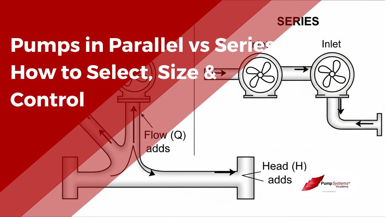
New engineers face the same early design decision again and again: should the station be arranged with pumps in parallel vs series? The choice sets the performance envelope, shapes the system curve intersection, and drives how the station will be controlled and protected for years. Getting it right requires linking pump curves with piping losses, then backing the selection with sensible control, instrumentation, and safeguards.
The sections below give a practical, engineering-first explanation aimed at students and junior pump engineers who want a grounded method, not just rules of thumb.
Pumps in Parallel vs Series: What’s the Difference
Parallel and series arrangements change how pump head and flow combine.
- In parallel, each pump sees the same discharge head, and flows add.
- In series, each pump handles the same flow, and heads add.
This simple idea is enough to predict the big-picture effect on the operating point, energy use, and control philosophy.
A compact comparison helps: Two practical reminders:
|
Aspect |
Parallel |
Series |
|---|---|---|
|
What adds |
Flow at a common head |
Head at a common flow |
|
Where it helps |
High-capacity, modest head, or widely varying demand |
High head at a given flow - series boosting |
|
Typical uses |
Municipal water, HVAC primary loops, process transfer, wastewater lift stations |
High-rise booster, mine dewatering, boiler feed, RO feed, pipeline booster |
|
Limits |
Little increase in peak head beyond a single pump’s shutoff head; manifold/header losses reduce ideal addition |
Flow capacity does not exceed that of one pump; piping and casings must tolerate higher pressure |
|
NPSH effect |
Each pump sees the same NPSHa; verify margin for all operating combinations |
Downstream stage benefits from higher suction pressure; first stage is critical for NPSHa vs NPSHr |
|
Valving |
Check valves on each branch to prevent reverse flow; isolation valves for service |
Non-return near each stage and, if needed, a bypass or balance line around an idle stage |
- Ideal doubling only happens for identical pumps without extra losses. Real systems have added header friction, fittings, and check valves that shave the sum.
- Curves matter. Parallel operation with “flat” or hump-backed curves can invite hydraulic instability. Series operation is more forgiving, yet each pump still must operate in a healthy region of its curve.
System Curve Interaction (How Flow & Head Add Up)
The operating point is the intersection of the combined pump curve with the system curve. The system curve captures static head plus friction losses, which often scale with the square of flow. Put differently: head vs flow for the system can be approximated as H = static head + k·Q².
- Adding a second identical pump in parallel shifts the composite pump curve to the right. At a given head, available flow rises. The new duty point slides to higher Q with roughly similar H.
- Placing a second identical pump in series shifts the composite curve upward. At a given flow, available head rises. The duty point climbs to higher H with similar Q.
A few practical effects follow from that geometry:
- Static-head dominated systems change little with parallel pumps because raising flow barely reduces the constant elevation component. Expect less-than-ideal flow addition.
- Friction-dominated systems respond well to added parallel capacity, since the higher Q is balanced against rising k·Q², which settles at a new, predictable duty point.
- Series boosting in a system with large static head can be decisive, since higher composite head overcomes the fixed elevation term cleanly.
Always plot the combined pump curve against the actual system curve that includes manifold/header losses, fittings, and any control valve pressure drop. That plot locates the true duty point.
Sizing & Selection Steps
A repeatable process keeps selection on track.
1. Define the Target Duty Point
-
Establish required flow, total dynamic head, and an operating range if demand varies.
-
Estimate static head and friction losses by segment to obtain the system curve.
-
Decide whether parallel capacity or series boosting better fits the specification and site constraints.
2. Check NPSHa vs NPSHr
-
Compute NPSHa (Net Positive Suction Head Available) at the pump suction under the worst credible conditions: lowest liquid level, highest temperature, longest suction line, and fouled strainers.
-
For parallel sets, confirm that each pump has adequate NPSHa margin across all staging combinations.
-
For series sets, pay special attention to the first pump in line (the limiter).
3. Aim near BEP for Reliability and Efficiency
-
Select pumps whose BEP (Best Efficiency Point) is close to the duty point.
-
Operating far left (near shutoff head) or far right (near runout) raises vibration and reduces life.
-
If demand varies widely, parallel pumps can keep each running unit near BEP by staging, or by speed control (VFD) at part load.
4. Apply the Affinity Laws Wisely
-
If a catalog curve is close but not perfect, consider impeller trimming or speed control (VFD).
-
Flow scales roughly with speed.
-
Head scales with speed squared.
-
Power scales with speed cubed.
-
-
Trimming is fixed and may reduce peak efficiency slightly; VFDs allow continuous tuning and can improve part-load efficiency.
5. Design the Headers, Balance Line, and Valves
-
Oversize common suction and discharge headers to minimize manifold/header losses and keep branch pressures uniform.
-
In parallel, include check valves and isolation valves on each branch. A short equalizing balance line across the suction header ends can help equalize suction pressure in large stations.
-
In series, ensure intermediate piping and seals are rated for the higher interstage pressure and consider a bypass around a stage that may be taken offline.
6. Choose a Control Strategy Up Front
-
Parallel pump control often uses lead/lag staging with setpoints tied to pressure or flow. Decide whether one VFD plus fixed-speed auxiliaries or all-VFD control fits best.
-
Series control often uses a VFD on the final stage to hold discharge pressure while upstream pumps run at fixed speed.
7. Validate Runout and Shutoff Edges
-
Confirm the combined curve cannot drive the operating point beyond safe runout (maximum flow) if a valve opens or a filter element fails.
-
Verify that minimum flow at high head will not force operation near shutoff head for extended periods.
Control & Protection
Control keeps the station on its intended curve. Protection keeps it intact when conditions stray.
- VFD strategies
- Parallel: each pump on a VFD enables smooth load sharing and precise parallel pump control. A typical lead/lag scheme runs one unit until a speed or flow threshold, then brings on a lag unit and lowers both speeds to share load near BEP.
- Series: a VFD on the last stage with a discharge pressure transmitter is common. The upstream stage runs constant speed to guarantee suction conditions for the booster.
- Throttling and minimum flow
- Throttling can modulate flow but wastes energy. Favor speed control for normal regulation and reserve throttling for fine trim or as a protective limit.
- Install a minimum-flow bypass sized per manufacturer guidance to avoid low-flow heating, recirculation, and vibration. Automatic recirculation valves are often used on multistage units.
- Surge, cavitation, and hydraulic instability
- Avoid abrupt starts and stops. Use soft starts and slow-closing valves to mitigate water hammer in headers and interstage piping.
- Watch NPSHa vs NPSHr under hot or low-level conditions. Cavitation erodes impellers and degrades head long before visible damage.
- In parallel, avoid pairing pumps with flat or unstable curves. That pairing can cause hunting, uneven load sharing, and noisy operation.
- Instrumentation and interlocks
- Install suction and discharge pressure transmitters on each pump or at least on the shared headers.
- Add flow measurement on the common discharge and, where feasible, on each branch to observe load sharing.
- Protect with trips or alarms for low suction pressure, high vibration, overtemperature, and motor overload. Interlock starts to prevent a pump from starting against a closed discharge.
FAQs:
Q1: When should I use pumps in parallel instead of series?
A1: Use parallel when the required capacity exceeds one pump or when demand varies widely and redundancy is desired. Use series when discharge pressure must exceed what one pump can deliver at the target flow.
Q2: How do flow and head combine in parallel vs series?
A2: Parallel adds flows at a common head. Series adds heads at a common flow.
Q3: How does the system curve change when I add a second pump?
A3: The system curve does not change. The composite pump curve shifts: rightward for parallel, upward for series. The duty point moves to the new intersection.
Q4: What’s the impact on NPSH and cavitation risk in each arrangement?
A4: Parallel leaves NPSHa unchanged for each pump, so check margin for all staging cases. In series, the downstream stage sees higher suction pressure, which improves its NPSH margin. The first stage is still the limiter.
Q5: How do I control parallel pumps (lead/lag, VFD, staging)?
A5: Run a lead pump up to a speed or flow target, then stage a lag pump and share load. VFDs on each pump simplify smooth sharing and reduce cycling.
Q6: How do I protect minimum flow and avoid runout in parallel?
A6: Install minimum-flow bypass protection, define staging bands that keep each unit near BEP, and confirm the combined curve cannot push the station past runout if the system head drops.
Q7: What check-valve and header layout is recommended?
A7: Put a check valve and an isolation valve on each branch discharge in parallel. Use large, short headers to limit losses and keep branch pressures uniform. In series, consider a non-return and a bypass around any stage that might be offline.
Q8: Can I mix different pump models/impellers in parallel or series?
A8: Mixing in parallel often causes poor load sharing and instability. If mixing is unavoidable, use VFDs and flow feedback to balance. In series, differences are less risky, but both stages still must operate in healthy regions of their curves.
Q9: How do affinity laws help when trimming or changing speed?
A9: They predict how flow, head, and power scale with speed or impeller diameter, which is valuable when fine-tuning a selected pump to land on the desired duty point.
Q10: Common troubleshooting: hunting/instability, reverse flow, no head gain—what to check?
A10: Check for flat or unstable curves, failed check valves, undersized or plugged headers, low NPSH, and a non-running stage. Verify pressures across each pump, compare to the curves, and correct the root cause.
