Pump Cavitation Prevention: Strategies for Longer Service Life
Aug 27, 2025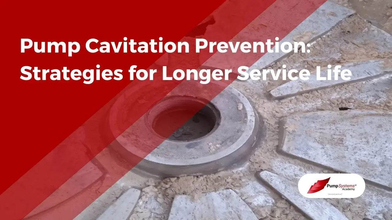
Is cavitation eroding your pump’s performance and reliability?
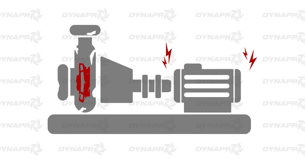
Cavitation is a silent threat. It can reduce pump efficiency, increase vibration and noise, and lead to severe damage to the impeller, casing, and other components. This phenomenon, caused by vapor bubble implosions at low-pressure zones, can incapacitate centrifugal pumps, shortening their lifespan and disrupting system performance.
1. Understanding Cavitation in Centrifugal Pumps
Cavitation silently undermines pump efficiency.
Five primary types of cavitation occur.
Vaporization, turbulence, vane syndrome, internal recirculation, and air aspiration cavitation each have unique mechanisms and effects. Understanding these distinctions is pivotal for diagnosing and addressing cavitation issues effectively.
Cavitation must be comprehended not merely as an operational nuisance but as a critical factor in pump longevity. A nuanced understanding of cavitation phenomena facilitates targeted interventions, ensuring sustained performance and mitigating the risk of costly repairs and downtime.
2. Types of Cavitation
Cavitation in centrifugal pumps manifests in several distinct forms, each stemming from different underlying causes.
- Vaporization: Also known as “classic cavitation” or “inadequate net positive suction head available (NPSHa) cavitation,” this occurs when a centrifugal pump increases the velocity of a fluid as it passes through the eye of the impeller. The increased velocity corresponds to a pressure reduction of the fluid, causing some of the fluid to boil (vaporize) and create tiny shock waves as the vapor bubbles collapse.
- Turbulence: Parts of a piping system such as elbows, valves, filters, or strainers may not be suitable for the amount or nature of liquid being pumped. This can create vortices, turbulent flow, and pressure differences throughout the liquid. When present at a pump inlet, these phenomena can erode pump internals directly or result in vaporization of the fluid.
- Vane Syndrome: Also known as “vane passing syndrome,” this type of cavitation occurs when an impeller is too large in diameter or the housing internal coating is too thick. Either one or both of these scenarios may reduce the space within the housing to below an acceptable level. The reduced clearance in the housing results in increased fluid velocity, leading to lower pressure and potential vaporization, creating cavitation bubbles.
- Internal Recirculation: This occurs when a pump cannot discharge fluid at the required rate, causing some or all of the fluid to recirculate around the impeller. The recirculating fluid passes through low and high-pressure zones, resulting in heat generation, high velocity, and the formation of vaporization bubbles. A common cause of internal recirculation is running the pump while a discharge valve is closed.
- Air Aspiration Cavitation: Air may be sucked into a pump through failing valves or loose joints. Once inside, the air flows along with the fluid. The movement of the fluid and air may result in the formation of air bubbles, which “explode” when exposed to increased pressure by the pump impeller.
Identifying the type of cavitation is crucial for implementing effective prevention strategies. These distinctions enable tailored diagnostics and solutions to improve pump longevity.
2.1 Vaporization Cavitation
Vaporization cavitation is the most common type, occurring when fluid pressure drops below vapor pressure.
Vapor bubbles in vaporization cavitation implode violently, causing severe mechanical damage to pump components.
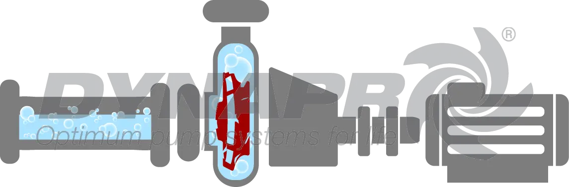
As the centrifugal pump increases fluid velocity, pressure decreases, allowing the fluid to boil and form vapor bubbles. These bubbles collapse when exposed to higher pressures, generating shock waves.
Preventing vaporization cavitation involves ensuring adequate net positive suction head available (NPSHa). This prevents fluid from vaporizing within the pump, thereby protecting essential components from damage.
Identifying vaporization cavitation involves recognizing specific symptoms and conditions within the pump system. Vaporization cavitation, also known as "classic cavitation" or "inadequate net positive suction head available (NPSHa) cavitation," occurs when the fluid pressure drops below its vapor pressure, causing the fluid to boil and form vapor bubbles. This list should be your first steps whenever you think you have any type of cavitation. Here’s how to identify it:
- Unusual Noise: Listen for a distinct noise resembling gravel or marbles rattling inside the pump. This sound is caused by the collapse of vapor bubbles as they move from low-pressure to high-pressure areas within the pump.
- Vibration: Monitor the pump for excessive vibration. The implosion of vapor bubbles generates shock waves that can cause the pump to vibrate abnormally.
- Reduced Performance: Observe any decline in pump performance, such as decreased flow rate or head. Vaporization cavitation can impair the pump’s efficiency by disrupting the smooth flow of fluid.
- Fluctuating Flow Rates: Check for inconsistent or fluctuating flow rates. The formation and collapse of vapor bubbles can cause irregularities in the fluid flow.
- Visual Inspection: Inspect the impeller and other internal components for signs of damage, such as pitting or erosion. The collapse of vapor bubbles can erode metal surfaces, leading to visible wear and tear.
- Pressure Measurement: Measure the pressure at the pump inlet and compare it to the fluid’s vapor pressure. If the inlet pressure is close to or below the vapor pressure, vaporization cavitation is likely occurring.
- Temperature Check: Assess the temperature of the fluid being pumped. Higher fluid temperatures can lower the vapor pressure, increasing the likelihood of vaporization cavitation.
By systematically evaluating these indicators, operators can identify vaporization cavitation and take appropriate measures to mitigate its effects, ensuring the longevity and efficiency of the pump system.
2.2 Turbulence-Induced Cavitation
Turbulence-induced cavitation results from improper piping components or installations that generate vortices and turbulent flow.
- Mismatched piping components like elbows and valves
- High fluid velocities causing pressure fluctuations
- Inadequate flow designs leading to vortex formation
- Blocked or partially closed filters and strainers
These turbulent conditions can erode pump internals and cause cavitation.
Minimizing turbulence involves proper system design and avoiding unnecessary flow restrictions.
Identifying turbulence-induced cavitation involves recognizing specific symptoms and conditions within the pump system that indicate the presence of turbulent flow. Turbulence-induced cavitation occurs when parts of the piping system, such as elbows, valves, filters, or strainers, create vortices and pressure differences that lead to the formation of vapor bubbles. Here’s how to identify it, with measures different than identifying Vaporization Cavitation:
- Pressure Measurement: Measure the pressure at various points in the piping system, especially near elbows, valves, filters, or strainers. Significant pressure drops in these areas can indicate turbulent flow conditions conducive to cavitation.
- Flow Visualization: Use flow visualization techniques, such as dye injection or computational fluid dynamics (CFD) modeling, to identify areas of turbulent flow within the piping system. These techniques can help pinpoint regions where cavitation is likely to occur.
- System Design Review: Evaluate the design of the piping system for potential sources of turbulence. Look for sharp bends, sudden changes in pipe diameter, or improperly sized fittings that could create turbulent flow conditions.
By systematically evaluating these indicators, operators can identify turbulence-induced cavitation and take appropriate measures to mitigate its effects, ensuring the longevity and efficiency of the pump system.
2.3 Vane Syndrome Cavitation
Vane syndrome cavitation, also known as "vane passing syndrome," occurs when the impeller is oversized. The diameter of the impeller or thickness of the housing’s internal coating reduces clearance.
When space within the housing is insufficient, fluid velocity increases, reducing pressure.
This pressure drop causes fluid vaporization, resulting in cavitation bubbles. These bubbles lead to impulses that can erode pump internals, thereby decreasing efficiency and longevity.
Optimal pump design considers impeller sizing and housing clearance, ensuring adequate space to minimize fluid acceleration and pressure drops. Adequate clearance and proper material selection in the impeller and casing also play vital roles in reducing vane syndrome cavitation.
Identifying vane syndrome cavitation, also known as "vane passing syndrome," involves recognizing specific symptoms and conditions within the pump system that indicate the presence of cavitation caused by impeller design issues. Vane syndrome cavitation occurs when an impeller is too large in diameter or the housing internal coating is too thick, reducing the space within the housing and increasing fluid velocity, leading to cavitation. Here’s how to identify it, with measures different than identifying Vaporization Cavitation:
- Pressure Measurement: Measure the pressure at the pump inlet and outlet. A significant pressure drop across the impeller can indicate high fluid velocity and reduced pressure, conditions conducive to vane syndrome cavitation.
- Impeller and Housing Inspection: Examine the impeller for signs of excessive size or the housing for overly thick internal coatings. These conditions can reduce the clearance within the housing, increasing fluid velocity and lowering pressure.
- System Design Review: Evaluate the design of the pump system, particularly the impeller and housing dimensions. Ensure that the impeller size and housing clearance are within acceptable limits to prevent high fluid velocity and reduced pressure.
By systematically evaluating these indicators, operators can identify vane syndrome cavitation and take appropriate measures to mitigate its effects, ensuring the longevity and efficiency of the pump system.
2.4 Internal Recirculation Cavitation
Internal recirculation cavitation occurs when a pump cannot discharge fluid at the required rate. As a consequence, fluid recirculates around the impeller.
Recirculation subjects the fluid to high velocity, heat generation, and temperature fluctuations. Hence, vaporization bubbles form.
A common cause is running the pump while the discharge valve is closed. This leads to fluctuations across low and high pressure zones.
Operators must ensure pumps avoid overworking under startup or shutdown conditions. Effective measures include maintaining proper discharge rates and employing control mechanisms to regulate flow. Regular maintenance and inspection also mitigate the risk associated with internal recirculation cavitation.

Identifying internal recirculation cavitation involves recognizing specific symptoms and conditions within the pump system that indicate the presence of cavitation caused by fluid recirculating around the impeller. Internal recirculation cavitation occurs when a pump cannot discharge fluid at the required rate, causing some or all of the fluid to recirculate through low and high-pressure zones, leading to the formation of vapor bubbles. Here’s how to identify it, with measures different than identifying Vaporization Cavitation:
- Pressure Measurement: Measure the pressure at the pump inlet and outlet. Significant pressure fluctuations can indicate the presence of recirculating fluid, which is a condition conducive to internal recirculation cavitation.
- Flow Rate Monitoring: Monitor the flow rate to ensure it meets the pump’s required discharge rate. If the flow rate is significantly lower than expected, it may indicate that fluid is recirculating within the pump.
- Discharge Valve Check: Ensure that the discharge valve is fully open and not restricting the flow. Running the pump with a partially closed or closed discharge valve can cause internal recirculation.
- System Design Review: Evaluate the design of the pump system, particularly the discharge piping and valve configuration. Ensure that the system is designed to allow the pump to discharge fluid at the required rate without causing recirculation.
By systematically evaluating these indicators, operators can identify internal recirculation cavitation and take appropriate measures to mitigate its effects, ensuring the longevity and efficiency of the pump system.
2.5 Air Aspiration Cavitation
Air aspiration cavitation is a significant issue that can severely impact pump performance and longevity.
This type of cavitation arises when air is introduced into the pump's suction line. The presence of air can result from improperly sealed pipe connections.
When air enters the pump, it forms bubbles that travel along with the fluid. As these bubbles are subjected to the pump's pressure increase, they implode.
The implosion of these air bubbles can cause substantial damage to the internal components of the pump. Using proper sealing techniques can mitigate this issue.
Regular inspection of valves and joints ensures they remain airtight, reducing the likelihood of air aspiration cavitation.
Identifying air aspiration cavitation involves recognizing specific symptoms and conditions within the pump system that indicate the presence of air being sucked into the pump. Air aspiration cavitation occurs when air enters the pump through failing valves, loose joints, or other leaks, leading to the formation of air bubbles that collapse violently under pressure. Here’s how to identify it, with measures different than identifying Vaporization Cavitation:
- Air Entrapment: Look for signs of air entrapment in the fluid, such as frothy or bubbly liquid at the pump discharge. This can indicate that air is being sucked into the pump.
- Leak Detection: Inspect the suction line, valves, and joints for any signs of leaks or loose connections. Air can enter the pump through these points, leading to cavitation.
- Priming Issues: Ensure that the pump is properly primed. Improper priming can introduce air into the pump, causing air aspiration cavitation.
- System Design Review: Evaluate the design of the pump system, particularly the suction piping and valve configuration. Ensure that the system is designed to minimize the risk of air being sucked into the pump.
By systematically evaluating these indicators, operators can identify air aspiration cavitation and take appropriate measures to mitigate its effects, ensuring the longevity and efficiency of the pump system.
3. Factors Contributing to Cavitation
Several key factors contribute to cavitation in centrifugal pumps, impacting the operational efficiency and longevity of these critical components. Among these are issues related to NPSH, air entrainment, and the alignment of pump and system curves, all of which profoundly influence the formation of cavitation bubbles.
Ensuring optimal operating conditions and addressing these contributing factors is vital in minimizing the risks associated with cavitation.
3.1 NPSH, NPSHa, and NPSHr
NPSH is a critical factor in preventing cavitation in centrifugal pumps.
- NPSH (Net Positive Suction Head): It measures the difference between actual suction pressure and a fluid's vapor pressure at the pump inlet.
- NPSHa (Net Positive Suction Head available): This denotes the actual suction head available during pump operation, factoring in the system conditions.
- NPSHr (Net Positive Suction Head required): It represents the minimum suction head required by the pump to prevent cavitation, as specified by the manufacturer.
NPSHa must always exceed NPSHr to avoid cavitation.
Proper calculation of NPSH values during design ensures reliable pump performance.
3.2 Air Entrainment
Air entrainment occurs when air is introduced into the pump's suction line, increasing cavitation risks.
- Ensure proper sealing of pipe connections.
- Avoid turbulent flow at the pump intake.
- Maintain positive suction head.
- Adhere to minimum submergence requirements.
- Regularly inspect suction lines for leaks.
Air in the liquid forms bubbles that exacerbate cavitation.
Reducing air entrainment is crucial in minimizing cavitation risks.
3.3 Pump and System Curve Analysis
The analysis of pump and system curves is essential for optimal pump performance.
By examining these curves, operators can identify the most efficient operating range and detect potential cavitation zones. This knowledge can improve the maintenance and operational planning of pumping systems.
Pump curves display a pump's head, flow rate, and efficiency under various conditions, essential for pinpointing the cavitation-prone regions. Meanwhile, system curves illustrate how the system's resistance changes with flow rate.
A critical intersection occurs where the pump curve meets the system curve, determining the actual operating point. Correctly interpreting this intersection helps in selecting the right pump and adjusting existing ones.
Operators and engineers who understand these dynamics can minimize cavitation risks, thereby extending pump life.
4. Strategies to Reduce Cavitation
Increasing NPSHa to prevent cavitation involves various strategies, including reducing the pump’s elevation relative to the suction reservoir and increasing suction pipe diameter. This ensures the pump operates above the critical NPSHr, thus averting cavitation.
Engineers should also consider impeller design modifications and implement flow control methods like bypass lines to maintain minimum flow rates. Such modifications distribute flow evenly across the impeller, reducing the likelihood of vapor bubble formation.
Employing anti-cavitation devices and ensuring proper pump sizing are essential. These measures will significantly enhance pump longevity.
4.1 Increasing NPSHa
Increasing the Net Positive Suction Head Available (NPSHa) is pivotal in the fight against cavitation.
One effective method is to reduce the pump's elevation relative to the suction reservoir, thus increasing inlet pressure.
Enhancing the suction pipe diameter also mitigates pressure drops, ensuring the fluid remains above vapor pressure levels.
Strategically reducing head loss within the suction line by optimizing fittings can provide significant benefits.
Such measures not only improve pump efficiency but also ensure its longevity.
4.2 Maintaining NPSH Margin
Maintaining a sufficient NPSH margin is critical in preventing cavitation and ensuring pump reliability.
- Maximize Suction Pressure: Increase suction pressure by lowering the pump's elevation.
- Enhance Pipe Diameter: Use larger diameter pipes to reduce friction losses.
- Optimize Pipe Fittings: Install low-resistance fittings to diminish pressure drops.
- Regular Monitoring: Continuously monitor and adjust based on real-time data.
A larger NPSH margin provides a safety buffer against fluctuating operating conditions.
Proper NPSH margin calculations enhance pump performance and longevity.
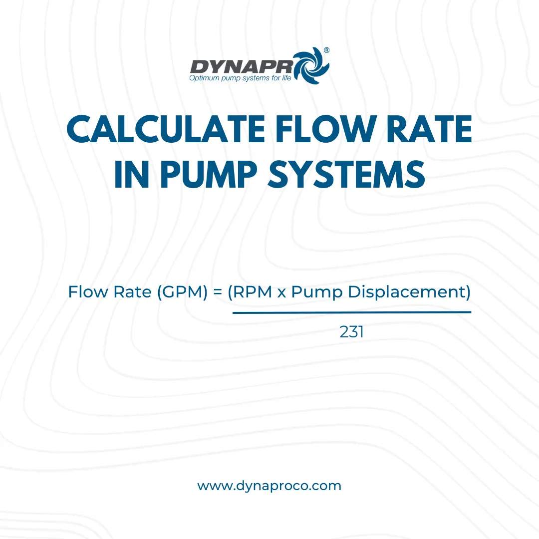
4.3 Ensuring Minimum Flow Rates
Minimum flow rates are crucial for centrifugal pumps.
Operating below the designated minimum flow rate can cause severe damage. Centrifugal pumps must maintain a specific flow rate to prevent cavitation, which can lead to the rapid deterioration of internal components. By adhering to manufacturers' recommended minimum flow rates, facilities can safeguard against unexpected downtime.
Utilizing control valves aids in flow regulation.
Automatic control systems can adjust the pump's operating conditions to ensure consistent flow. Incorporating variable speed drives provides additional flexibility to meet varying process demands without compromising the pump's efficiency.
Flow monitoring setups should be implemented.
These systems enable real-time data tracking and ensure that the pumps operate within safe parameters. Regular assessment of flow rates and system performance forms the backbone of proactive maintenance strategies aimed at optimizing pump operation and preventing cavitation.
4.4 Optimizing Impeller Design
Impeller design is crucial for minimizing cavitation, enhancing pump performance, and ensuring durability under various conditions.
Optimizing impeller design involves selecting a configuration with fewer, larger blades to reduce fluid acceleration, thereby decreasing the likelihood of cavitation. Additionally, impellers with larger inlet diameters or tapered blades smooth out fluid flow, minimizing turbulence and vapor bubble formation. Employing materials designed to withstand cavitation damage further extends the impeller’s operational lifespan and efficacy.
Precision in impeller design ensures maximum efficiency. By fine-tuning blade angles, reducing sharp transitions, and considering the fluid’s properties, engineers can achieve optimal pump performance with reduced cavitation risk. These alterations lead to improved hydraulic balance and overall pump stability.
Furthermore, incorporating sophisticated analysis, such as Computational Fluid Dynamics (CFD), allows engineers to predict and mitigate potential cavitation zones. This approach enables precise adjustments tailored to specific applications, increasing reliability and reducing maintenance frequency. Employing innovative design methods to refine impeller characteristics ensures pumps operate efficiently and withstand demanding operational conditions.

4.5 Using Anti-Cavitation Devices
Utilizing anti-cavitation devices, such as flow modification attachments, can significantly improve pump performance by reducing the occurrence of cavitation. These devices operate by controlling fluid dynamics.
Flow straighteners are particularly effective in mitigating cavitation risks. They work by reducing the swirl components within the fluid, which can otherwise create turbulence.
By imposing a more laminar flow condition at the pump inlet, flow straighteners optimize the pressure distribution within the pump, minimizing the potential for vapor bubble formation.
Cavitation suppression liners are another useful tool in combating cavitation. These liners function by disrupting the implosion of vapor bubbles, preventing the resultant shock waves from damaging pump components.
In addition, some anti-cavitation devices are engineered to adjust the flow paths inside the pump. This ensures low-pressure zones are minimized, thereby decreasing the likelihood of vapor bubble formation.
Ultimately, the use of anti-cavitation devices is essential for enhancing pump longevity. Through strategic implementation, facilities can maintain reliable pump operations and reduce maintenance costs significantly.
Proper Pump Sizing
Proper pump sizing ensures optimal performance, preventing cavitation, managing temperature, and extending the pump's life.
When selecting a pump, it is imperative to match the system’s requirements with the pump capacity, considering factors such as maximum, normal, and minimum flow conditions. This precise alignment helps balance fluid dynamics and maintain the necessary pressure conditions to avoid cavitation, improving reliability significantly.
Detailed analysis of fluid properties and system layout is crucial in this process. Engineers should evaluate all operational scenarios and design parameters to choose the appropriately sized pump, thus facilitating seamless and efficient operation across varying system demands.
An oversized pump can lead to inefficient operation and heightened cavitation risk due to low flow conditions, while an undersized pump might overexert itself to meet system demands, increasing the likelihood of cavitation. Ensuring proper pump sizing enhances efficiency, promotes longevity, and fortifies overall system integrity.
Identifying Possible Situations with Cavitation
|
Symptoms |
Possible Cause |
Possible Solutions |
|---|---|---|
|
Excessive noise and vibration |
Vaporization due to low NPSHa |
Increase NPSHa by lowering pump elevation, increasing suction pipe diameter, or reducing head loss |
|
Reduced pump efficiency |
Air entrainment from leaks or improper priming |
Ensure proper sealing of pipe connections, maintain positive suction head, and avoid turbulent flow |
|
Impeller damage |
Internal recirculation due to closed discharge valve |
Avoid running the pump with a closed discharge valve, ensure proper flow control methods |
|
Erosion and corrosion of components |
Turbulence from unsuitable piping system components (elbows, valves, filters) |
Use appropriate fittings, reduce number of fittings, and ensure proper installation of components |
|
Sudden drop in pump performance |
Vane syndrome from oversized impeller or thick housing coating |
Ensure correct impeller size and appropriate housing coating thickness |
|
Presence of air bubbles |
Air aspiration through failing valves or loose joints |
Inspect and repair valves and joints, ensure proper sealing and maintenance |
|
High fluid temperature |
Heat generation from internal recirculation |
Maintain minimum flow rates, use bypass lines or control valves, and monitor pump operation |
|
Frequent maintenance issues |
Inadequate NPSH margin |
Calculate and maximize NPSH margin, regularly monitor and adjust based on real-time operating data |
|
Cavitation damage |
Incorrect pump sizing |
Perform detailed analysis of flow requirements, fluid properties, and system layout to ensure proper sizing |

People Also Ask
What is cavitation and why is it bad?
Cavitation is a detrimental occurrence in pumps.
It transpires when the fluid pressure dips below the vapor pressure, leading to vapor bubble formation. These bubbles, upon entering higher pressure areas, implode violently, causing destructive shock waves. Such implosions can erode impellers, casing, and other internal components, impairing pump efficiency.
This phenomenon often leads to noise and vibrations.
Damage incurred from cavitation translates directly to maintenance costs and unscheduled downtime. The weakened components become vulnerable to further erosion and corrosion, ultimately diminishing the pump's reliability and lifespan.
Properly addressing and preventing cavitation ensures that centrifugal pumps operate efficiently, reducing operational costs and enhancing the longevity of these crucial components in fluid systems.
Cavitation in pumps refers to the formation and collapse of vapor bubbles in the liquid being pumped. This occurs when the local pressure drops below the vapor pressure of the liquid, leading to the formation of vapor bubbles, which collapse violently as they move into higher pressure areas, causing damage to the pump components.
What causes cavitation in pumps?
Common causes of cavitation include inadequate net positive suction head (NPSH), high fluid temperatures, poor system design, high altitudes reducing atmospheric pressure, and obstructions in the suction line. Poorly designed piping systems and running the pump too far off its performance curve can also contribute to cavitation.
What are the symptoms of pump cavitation?
Symptoms of pump cavitation include unusual noise (similar to gravel or marbles in the pump), vibration, reduced pump performance, fluctuating flow rates, and damage to the impeller and other internal components, such as pitting or erosion.
How does cavitation damage a pump?
Cavitation causes physical damage to the pump components, such as pitting and erosion of the impeller and volute. The collapsing bubbles produce shock waves that can lead to metal fatigue, material loss, and ultimately, pump failure. This damage results in costly repairs and downtime.
How can cavitation be prevented?
Preventing cavitation involves ensuring proper suction conditions, optimizing impeller design, controlling fluid temperature, maintaining an adequate NPSH margin, checking for leaks, using appropriate materials for pump construction, and performing regular maintenance. Design considerations such as proper piping layout and pump selection also play crucial roles in preventing cavitation.
Can cavitation be corrected once it occurs?
Correcting cavitation typically requires addressing the root causes, which might involve redesigning the system, adjusting pump speed, increasing suction pressure, or replacing damaged components. Permanent solutions often include improving system design to meet NPSH requirements and ensuring optimal operating conditions.
What is the difference between cavitation and air entrainment?
Cavitation involves the formation and collapse of vapor bubbles within the liquid, while air entrainment refers to the introduction of air bubbles into the liquid. Both phenomena can cause damage to pumps, but cavitation typically results in quicker and more severe damage.
Understanding these aspects of pump cavitation helps in designing more efficient pump systems and implementing effective preventive measures.
Where can I find training on how to identify and solve pump cavitation?
For comprehensive training on how to identify pump cavitation, visit The Pump Systems Academy at www.pumpsystemsacademy.com. This resource offers detailed courses and expert guidance on recognizing and mitigating cavitation in pump systems.
